

导语
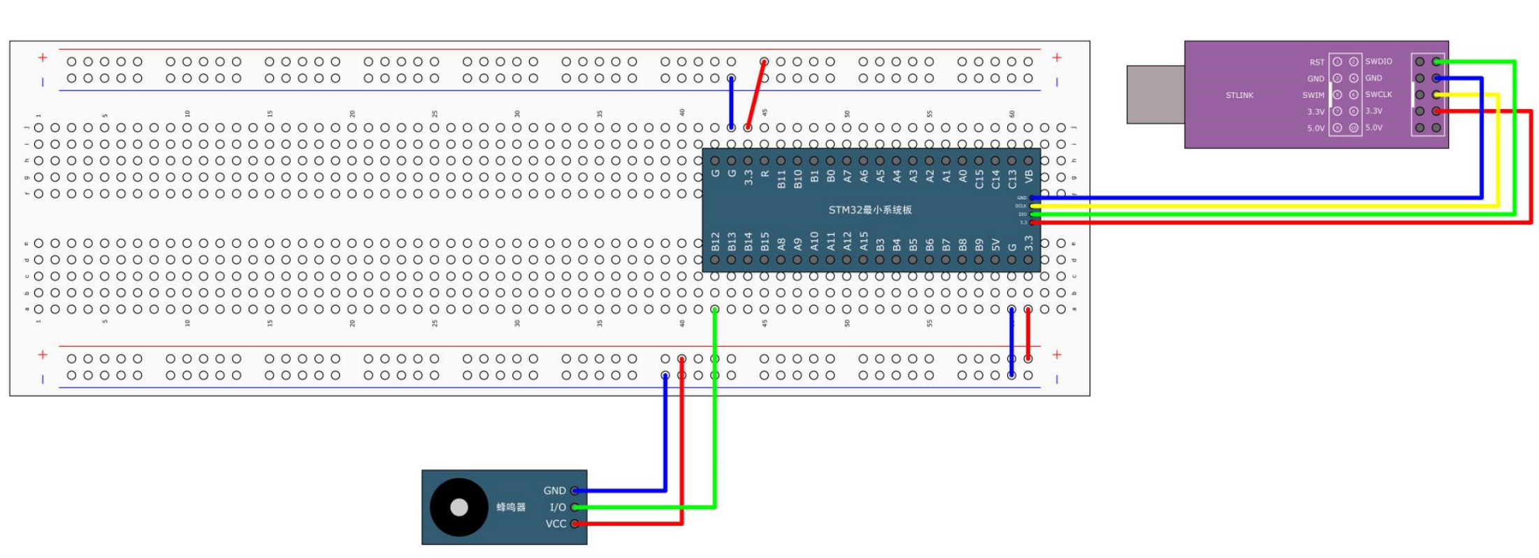
我们需要先搭建一下面包板电路,如下图所示:

RCC/GPIO库函数
我们之前说过,操作STM32的GPIO总共需要3个步骤,第一步,使用RCC开启GPIO的时钟;第二步,使用GPIO_Init函数初始化GPIO;第三步,使用输出或者输入的函数控制GPIO口。在这里总共涉及了RCC和GPIO两个外设。
RCC外设用到的最多的库函数
RCC AHB外设时钟控制:void RCC_AHBPeriphClockCmd(uint32_t RCC_AHBPeriph, FunctionalState NewState);
/**
  * @brief  Enables or disables the AHB peripheral clock.
  * @param  RCC_AHBPeriph: specifies the AHB peripheral to gates its clock.
  *
  *   For @b STM32_Connectivity_line_devices, this parameter can be any combination
  *   of the following values:
  *     @arg RCC_AHBPeriph_DMA1
  *     @arg RCC_AHBPeriph_DMA2
  *     @arg RCC_AHBPeriph_SRAM
  *     @arg RCC_AHBPeriph_FLITF
  *     @arg RCC_AHBPeriph_CRC
  *     @arg RCC_AHBPeriph_OTG_FS
  *     @arg RCC_AHBPeriph_ETH_MAC
  *     @arg RCC_AHBPeriph_ETH_MAC_Tx
  *     @arg RCC_AHBPeriph_ETH_MAC_Rx
  *
  *   For @b other_STM32_devices, this parameter can be any combination of the
  *   following values:
  *     @arg RCC_AHBPeriph_DMA1
  *     @arg RCC_AHBPeriph_DMA2
  *     @arg RCC_AHBPeriph_SRAM
  *     @arg RCC_AHBPeriph_FLITF
  *     @arg RCC_AHBPeriph_CRC
  *     @arg RCC_AHBPeriph_FSMC
  *     @arg RCC_AHBPeriph_SDIO
  *
  * @note SRAM and FLITF clock can be disabled only during sleep mode.
  * @param  NewState: new state of the specified peripheral clock.
  *   This parameter can be: ENABLE or DISABLE.
  * @retval None
  */
void RCC_AHBPeriphClockCmd(uint32_t RCC_AHBPeriph, FunctionalState NewState)
{
  /* Check the parameters */
  assert_param(IS_RCC_AHB_PERIPH(RCC_AHBPeriph));
  assert_param(IS_FUNCTIONAL_STATE(NewState));

  if (NewState != DISABLE)
  {
    RCC->AHBENR |= RCC_AHBPeriph;
  }
  else
  {
    RCC->AHBENR &= ~RCC_AHBPeriph;
  }
}
RCC APB2外设时钟控制:void RCC_APB2PeriphClockCmd(uint32_t RCC_APB2Periph, FunctionalState NewState);
/**
  * @brief  Enables or disables the High Speed APB (APB2) peripheral clock.
  * @param  RCC_APB2Periph: specifies the APB2 peripheral to gates its clock.
  *   This parameter can be any combination of the following values:
  *     @arg RCC_APB2Periph_AFIO, RCC_APB2Periph_GPIOA, RCC_APB2Periph_GPIOB,
  *          RCC_APB2Periph_GPIOC, RCC_APB2Periph_GPIOD, RCC_APB2Periph_GPIOE,
  *          RCC_APB2Periph_GPIOF, RCC_APB2Periph_GPIOG, RCC_APB2Periph_ADC1,
  *          RCC_APB2Periph_ADC2, RCC_APB2Periph_TIM1, RCC_APB2Periph_SPI1,
  *          RCC_APB2Periph_TIM8, RCC_APB2Periph_USART1, RCC_APB2Periph_ADC3,
  *          RCC_APB2Periph_TIM15, RCC_APB2Periph_TIM16, RCC_APB2Periph_TIM17,
  *          RCC_APB2Periph_TIM9, RCC_APB2Periph_TIM10, RCC_APB2Periph_TIM11
  * @param  NewState: new state of the specified peripheral clock.
  *   This parameter can be: ENABLE or DISABLE.
  * @retval None
  */
void RCC_APB2PeriphClockCmd(uint32_t RCC_APB2Periph, FunctionalState NewState)
{
  /* Check the parameters */
  assert_param(IS_RCC_APB2_PERIPH(RCC_APB2Periph));
  assert_param(IS_FUNCTIONAL_STATE(NewState));
  if (NewState != DISABLE)
  {
    RCC->APB2ENR |= RCC_APB2Periph;
  }
  else
  {
    RCC->APB2ENR &= ~RCC_APB2Periph;
  }
}
RCC APB1外设时钟控制:void RCC_APB1PeriphClockCmd(uint32_t RCC_APB1Periph, FunctionalState NewState);
/**
  * @brief  Enables or disables the Low Speed APB (APB1) peripheral clock.
  * @param  RCC_APB1Periph: specifies the APB1 peripheral to gates its clock.
  *   This parameter can be any combination of the following values:
  *     @arg RCC_APB1Periph_TIM2, RCC_APB1Periph_TIM3, RCC_APB1Periph_TIM4,
  *          RCC_APB1Periph_TIM5, RCC_APB1Periph_TIM6, RCC_APB1Periph_TIM7,
  *          RCC_APB1Periph_WWDG, RCC_APB1Periph_SPI2, RCC_APB1Periph_SPI3,
  *          RCC_APB1Periph_USART2, RCC_APB1Periph_USART3, RCC_APB1Periph_USART4,
  *          RCC_APB1Periph_USART5, RCC_APB1Periph_I2C1, RCC_APB1Periph_I2C2,
  *          RCC_APB1Periph_USB, RCC_APB1Periph_CAN1, RCC_APB1Periph_BKP,
  *          RCC_APB1Periph_PWR, RCC_APB1Periph_DAC, RCC_APB1Periph_CEC,
  *          RCC_APB1Periph_TIM12, RCC_APB1Periph_TIM13, RCC_APB1Periph_TIM14
  * @param  NewState: new state of the specified peripheral clock.
  *   This parameter can be: ENABLE or DISABLE.
  * @retval None
  */
void RCC_APB1PeriphClockCmd(uint32_t RCC_APB1Periph, FunctionalState NewState)
{
  /* Check the parameters */
  assert_param(IS_RCC_APB1_PERIPH(RCC_APB1Periph));
  assert_param(IS_FUNCTIONAL_STATE(NewState));
  if (NewState != DISABLE)
  {
    RCC->APB1ENR |= RCC_APB1Periph;
  }
  else
  {
    RCC->APB1ENR &= ~RCC_APB1Periph;
  }
}
GPIO外设用到的最多的库函数
void GPIO_DeInit(GPIO_TypeDef* GPIOx);
参数可以写GPIOA,GPIOB等等,调用这个函数之后,所指定的GPIO外设就会被复位,这就是这个函数的用途。
void GPIO_AFIODeInit(void);
可以复位AFIO外设。
void GPIO_Init(GPIO_TypeDef* GPIOx, GPIO_InitTypeDef* GPIO_InitStruct);
这个函数的作用是,用结构体参数来初始化GPIO口,我们需要先定义一个结构体变量,然后再给结构体赋值,最后调用这个函数,这个函数内部就会自动读取结构体的值,然后自动把外设的各个参数配置好,这种Init函数在STM32中基本所有的外设都有,一般我们初始化外设都是使用这个Init函数来完成的。
void GPIO_StructInit(GPIO_InitTypeDef* GPIO_InitStruct);
这个函数可以把结构体变量赋以一个默认值。
GPIO四个读取函数:
uint8_t GPIO_ReadInputDataBit(GPIO_TypeDef* GPIOx, uint16_t GPIO_Pin);
uint16_t GPIO_ReadInputData(GPIO_TypeDef* GPIOx);
uint8_t GPIO_ReadOutputDataBit(GPIO_TypeDef* GPIOx, uint16_t GPIO_Pin);
uint16_t GPIO_ReadOutputData(GPIO_TypeDef* GPIOx);
GPIO四个输出函数:
把指定的函数的端口设置为高电平:
void GPIO_SetBits(GPIO_TypeDef* GPIOx, uint16_t GPIO_Pin);
把指定的端口设置为低电平:
void GPIO_ResetBits(GPIO_TypeDef* GPIOx, uint16_t GPIO_Pin);
根据第三个参数的值来设置指定的端口:
void GPIO_WriteBit(GPIO_TypeDef* GPIOx, uint16_t GPIO_Pin, BitAction BitVal);
这个函数可以同时对16个端口进行写入操作:
void GPIO_Write(GPIO_TypeDef* GPIOx, uint16_t PortVal);
写代码
GPIO_InitTypeDef GPIOInitStructure;
GPIO的8种模式:
GPIO_Mode_AIN 模拟输入
GPIO_Mode_IN_FLOATING 浮空输入
GPIO_Mode_IPD 下拉输入
GPIO_Mode_IPU 上拉输入
GPIO_Mode_Out_OD 开漏输出
GPIO_Mode_Out_PP 推挽输出
GPIO_Mode_AF_OD 复用开漏
GPIO_Mode_AF_PP 复用推挽
我们点灯用的是推挽输出,所以用的是GPIO_Mode_Out_PP。
点亮LED代码:
#include "stm32f10x.h"

int main(void){
	RCC_APB2PeriphClockCmd(RCC_APB2Periph_GPIOA,ENABLE);
	GPIO_InitTypeDef GPIO_InitStructure;
	GPIO_InitStructure.GPIO_Mode = GPIO_Mode_Out_PP;
	GPIO_InitStructure.GPIO_Pin =GPIO_Pin_0;
	GPIO_InitStructure.GPIO_Speed = GPIO_Speed_50MHz;
	GPIO_Init(GPIOA,&GPIO_InitStructure); //GPIOA外设的0号引脚就自动被配置为推挽输出、50MHz的速度了。

	GPIO_ResetBits(GPIOA,GPIO_Pin_0);

	while(1){

	}
}
闪烁LED代码:
#include "stm32f10x.h"
#include "Delay.h"
int main(void){
	RCC_APB2PeriphClockCmd(RCC_APB2Periph_GPIOA,ENABLE);
	GPIO_InitTypeDef GPIO_InitStructure;
	GPIO_InitStructure.GPIO_Mode = GPIO_Mode_Out_PP;
	GPIO_InitStructure.GPIO_Pin =GPIO_Pin_0;
	GPIO_InitStructure.GPIO_Speed = GPIO_Speed_50MHz;
	GPIO_Init(GPIOA,&GPIO_InitStructure); //GPIOA外设的0号引脚就自动被配置为推挽输出、50MHz的速度了。

	GPIO_ResetBits(GPIOA,GPIO_Pin_0);

	while(1){
		GPIO_ResetBits(GPIOA,GPIO_Pin_0);
		Delay_ms(500);
		GPIO_SetBits(GPIOA,GPIO_Pin_0);
		Delay_ms(500);
	}
}
LED流水灯:

#include "stm32f10x.h"
#include "Delay.h"
int main(void){
	RCC_APB2PeriphClockCmd(RCC_APB2Periph_GPIOA,ENABLE);
	GPIO_InitTypeDef GPIO_InitStructure;
	GPIO_InitStructure.GPIO_Mode = GPIO_Mode_Out_PP;
	GPIO_InitStructure.GPIO_Pin =GPIO_Pin_All;
	GPIO_InitStructure.GPIO_Speed = GPIO_Speed_50MHz;
	GPIO_Init(GPIOA,&GPIO_InitStructure); //GPIOA外设的所有引脚就自动被配置为推挽输出、50MHz的速度了。

	while(1){
		GPIO_ResetBits(GPIOA,GPIO_Pin_0);
		Delay_ms(100);
		GPIO_SetBits(GPIOA,GPIO_Pin_0);
		Delay_ms(100);
		GPIO_ResetBits(GPIOA,GPIO_Pin_1);
		Delay_ms(100);
		GPIO_SetBits(GPIOA,GPIO_Pin_1);
		Delay_ms(100);
		GPIO_ResetBits(GPIOA,GPIO_Pin_2);
		Delay_ms(100);
		GPIO_SetBits(GPIOA,GPIO_Pin_2);
		Delay_ms(100);
		GPIO_ResetBits(GPIOA,GPIO_Pin_3);
		Delay_ms(100);
		GPIO_SetBits(GPIOA,GPIO_Pin_3);
		Delay_ms(100);
		GPIO_ResetBits(GPIOA,GPIO_Pin_4);
		Delay_ms(100);
		GPIO_SetBits(GPIOA,GPIO_Pin_4);
		Delay_ms(100);
		GPIO_ResetBits(GPIOA,GPIO_Pin_7);
		Delay_ms(100);
		GPIO_SetBits(GPIOA,GPIO_Pin_7);
		Delay_ms(100);
	}
}
蜂鸣器:
#include "stm32f10x.h"
#include "Delay.h"
int main(void){
	RCC_APB2PeriphClockCmd(RCC_APB2Periph_GPIOB,ENABLE);
	GPIO_InitTypeDef GPIO_InitStructure;
	GPIO_InitStructure.GPIO_Mode = GPIO_Mode_Out_PP;
	GPIO_InitStructure.GPIO_Pin =GPIO_Pin_12;
	GPIO_InitStructure.GPIO_Speed = GPIO_Speed_50MHz;
	GPIO_Init(GPIOB,&GPIO_InitStructure); //GPIOB外设的12引脚就自动被配置为推挽输出、50MHz的速度了。

	while(1){
		GPIO_ResetBits(GPIOB,GPIO_Pin_12);
		Delay_ms(1000);
		GPIO_SetBits(GPIOB,GPIO_Pin_12);
		Delay_ms(1000);
	}
}